LS Laird Scabar
All projects Project 01 — Mechanical design

SUBC Submarine Drivetrain

The human-powered drivetrain for UBC's competition submarine — redesigned to be half the weight with none of the gear slippage.

Team
SUBC — UBC Submarine Design Team
Timeline
2025 — 2026
My role
Drivetrain Engineer
Outcome
50% lighter gearbox
Longer, in-depth explanation Flip the switch for the full engineering breakdown

Quick explanation

What it is

  • SUBC builds human-powered submarines to race internationally — a diver inside pedals the sub through a course.
  • I owned the drivetrain: the gearbox that turns pedalling into propeller rotation.
  • Redesigning the side plates and step-down collar cut the gearbox weight in half and eliminated output gear slippage entirely.
  • Modelled in SolidWorks, validated with FEA, and CNC machined with a machinist.
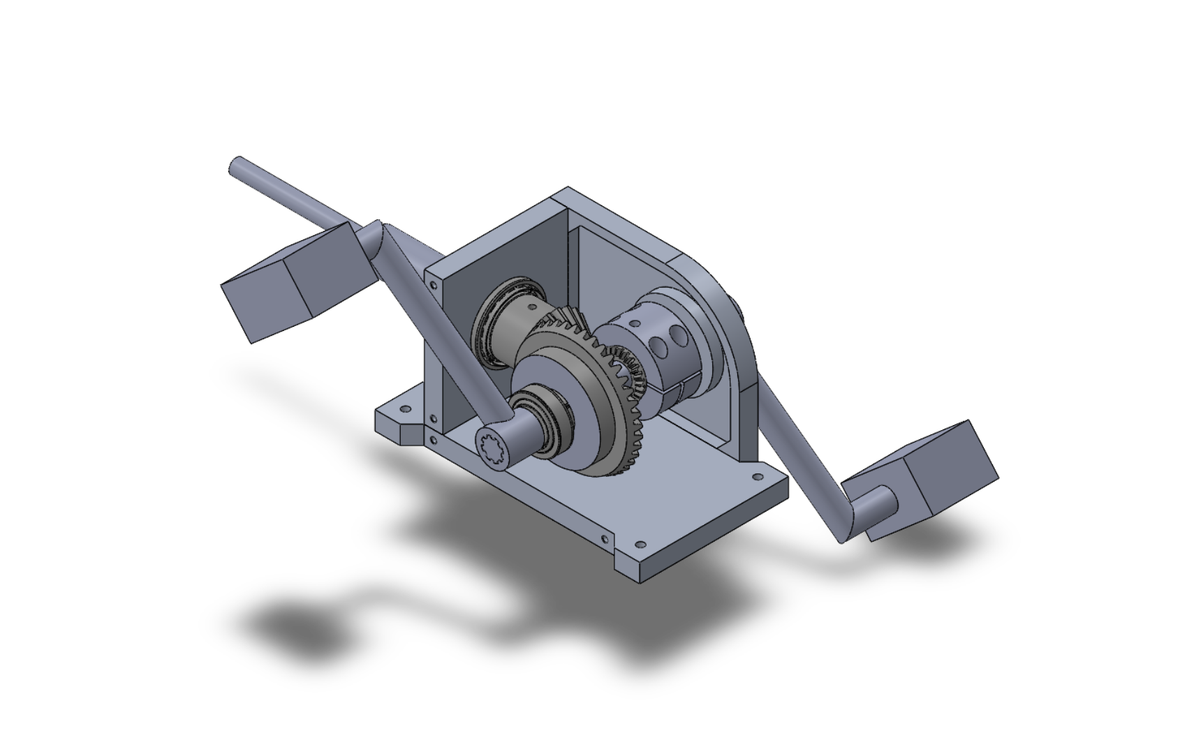
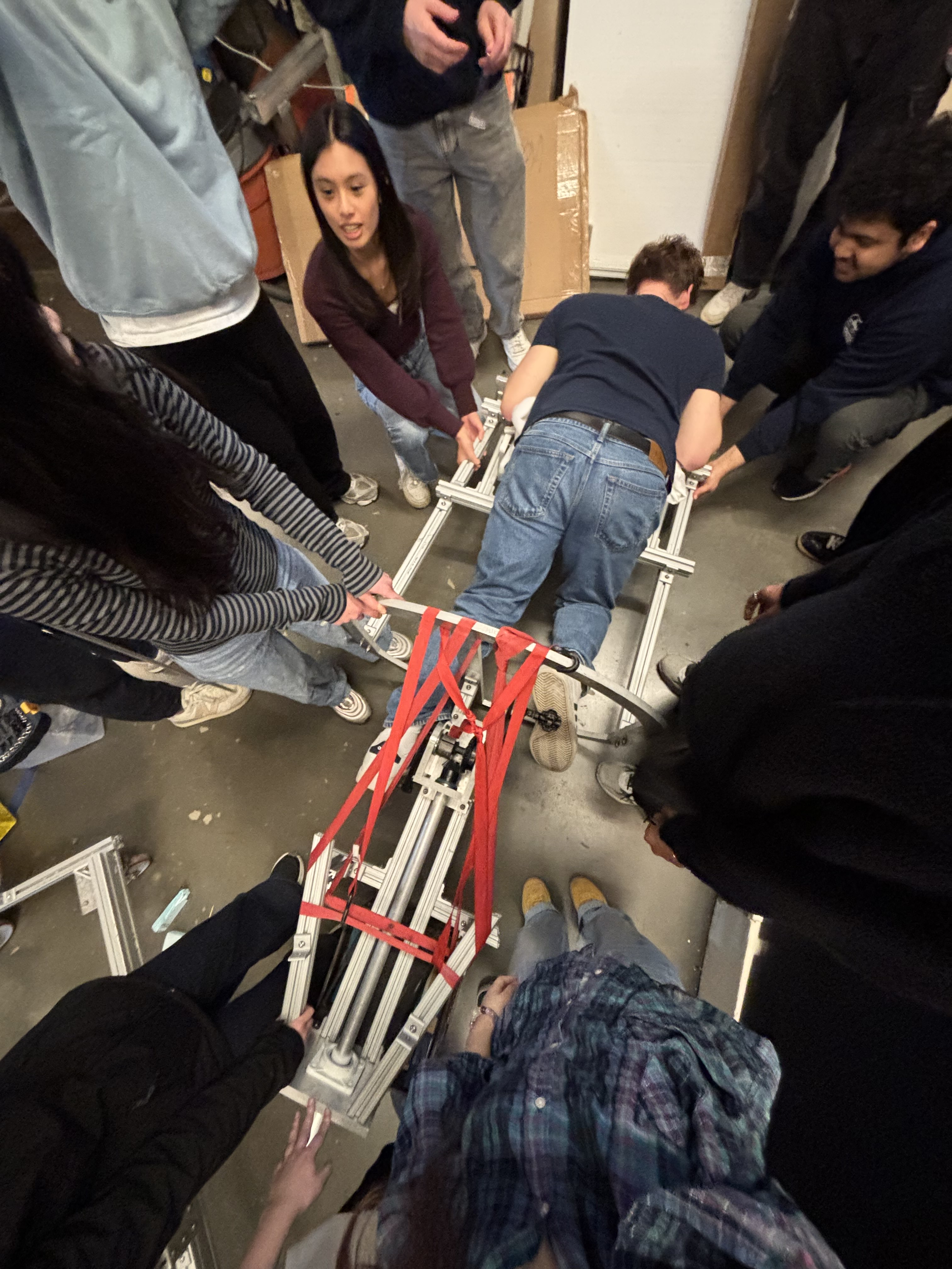
The assembled submarine drivetrain

Deep dive

How the drivetrain came together

Part 1: the problem

1. Two things were wrong with the old gearbox

  • It was heavier than it needed to be. The whole vehicle is buoyancy-balanced, so every gram of structure is a gram that has to be offset somewhere else.
  • The output gear slipped on its shaft under load — losing power at exactly the moment the pilot was pushing hardest, which is the worst possible time to lose it.
  • Both problems lived in the same two components: the side plates that carry the bearing bores, and the step-down collar that couples the output gear.

Part 2: concept & CAD

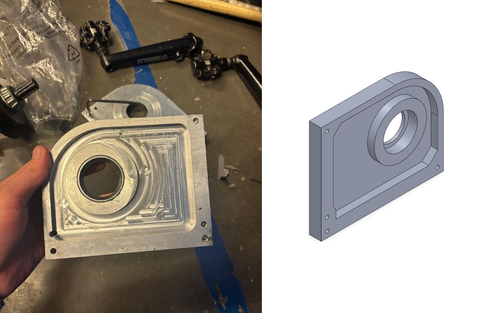
2. Generating and narrowing the side plate concepts

  • Generated several side plate concepts and scored them against weight, stiffness, and — critically — whether a machinist could actually fixture and cut them.
  • Modelled the shortlist in SolidWorks, iterating the geometry around the bearing bores and mounting interfaces where the loads concentrate.
  • Kept the bearing seats as the fixed reference and let everything else move, so alignment stayed correct through every revision.
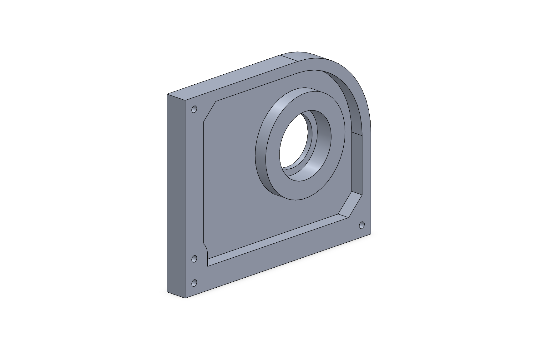
Side plate CAD model

Part 3: FEA optimization

3. Letting the analysis remove the material

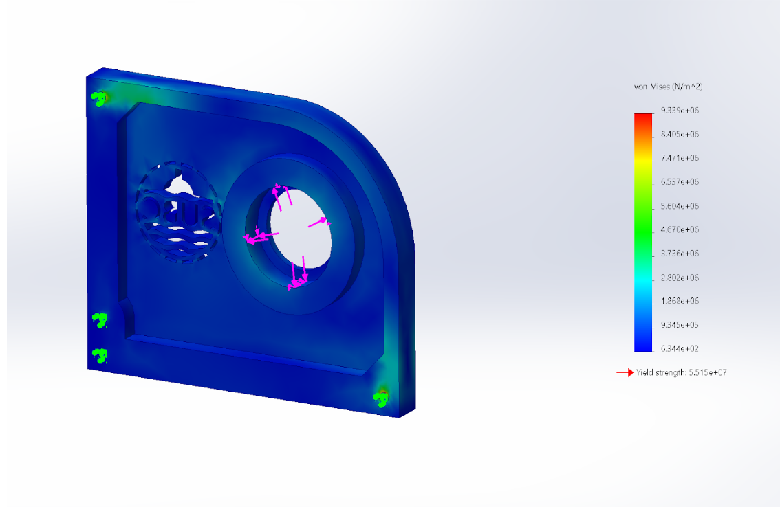
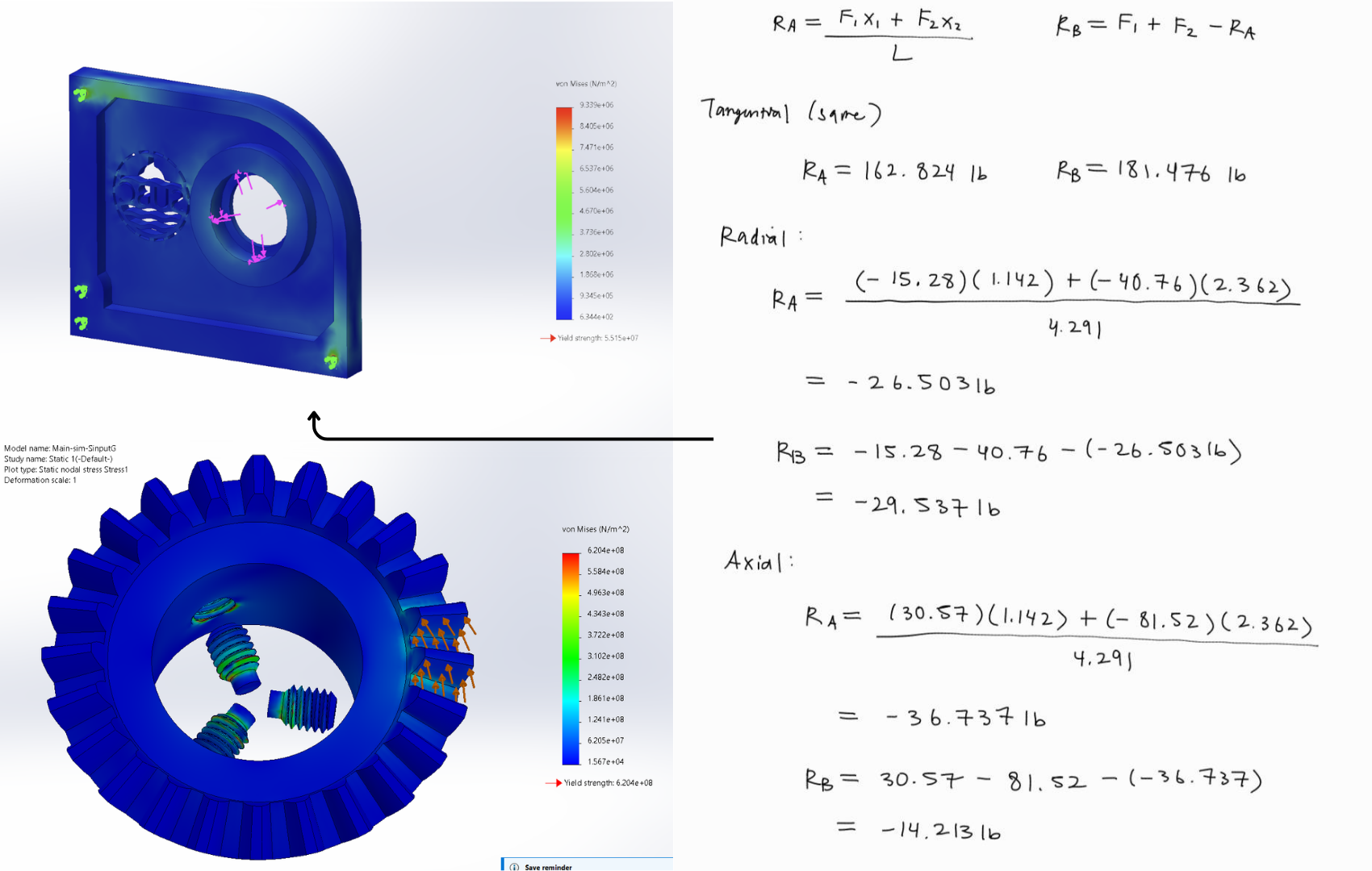
  • Ran FEA on each iteration and stripped material out of the low-stress regions the analysis highlighted.
  • Held deflection at the bearing seats as the hard constraint — past a certain flex the gears stop meshing correctly no matter how strong the plate is.
  • Several concepts I liked visually failed on deflection and had to be thrown out. This was the first project where FEA changed my design rather than just confirming it.
FEA stress analysis of the side plate

Part 4: fixing the slippage

4. Redesigning the step-down collar

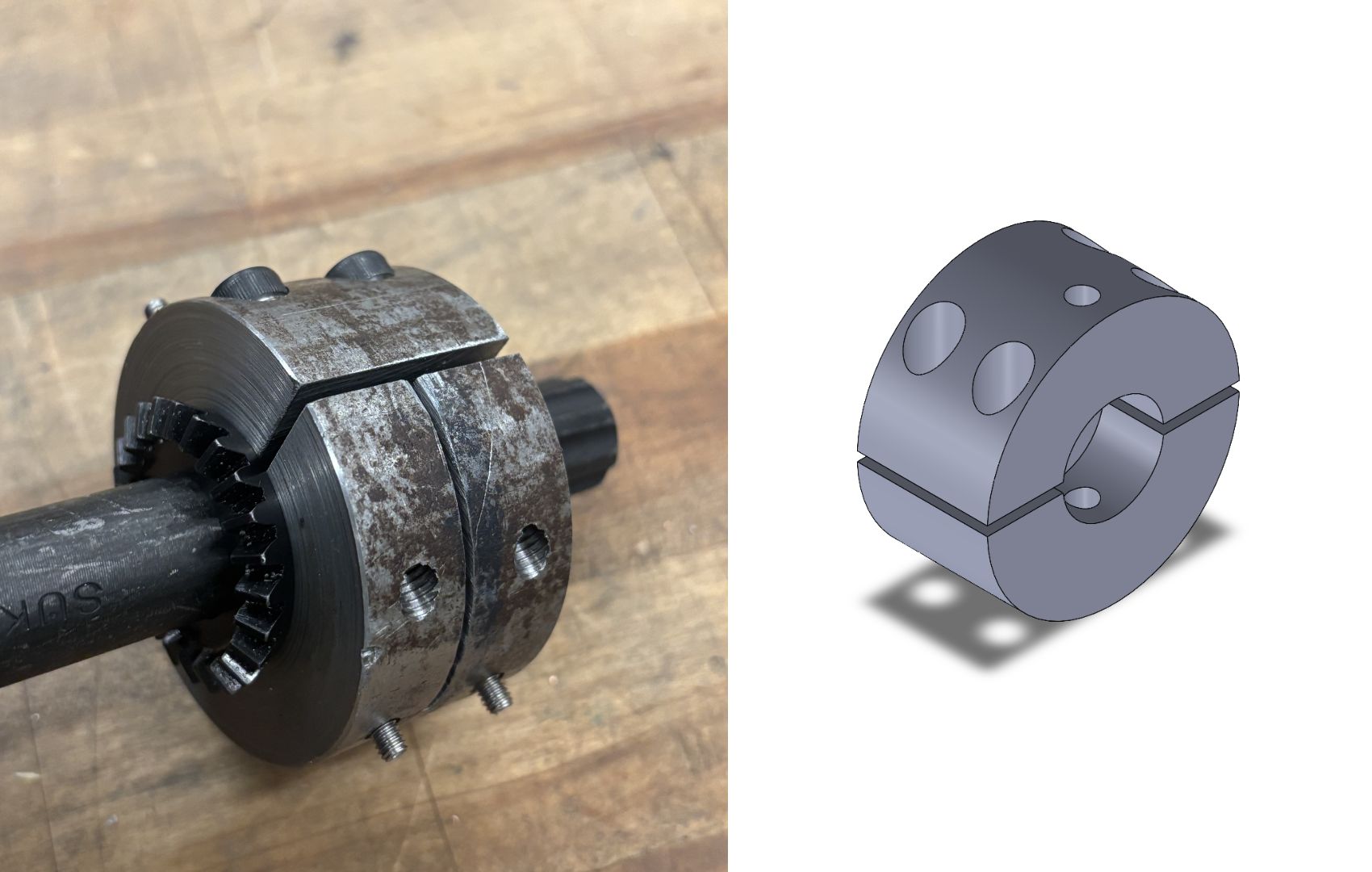
  • The original collar relied on friction alone to hold the output gear, which is why it let go under peak torque.
  • Redesigned the interface to positively lock the gear instead — a mechanical constraint rather than a clamping force that degrades.
  • Produced manufacturing drawings with GD&T callouts so the fits were unambiguous to whoever cut the part.
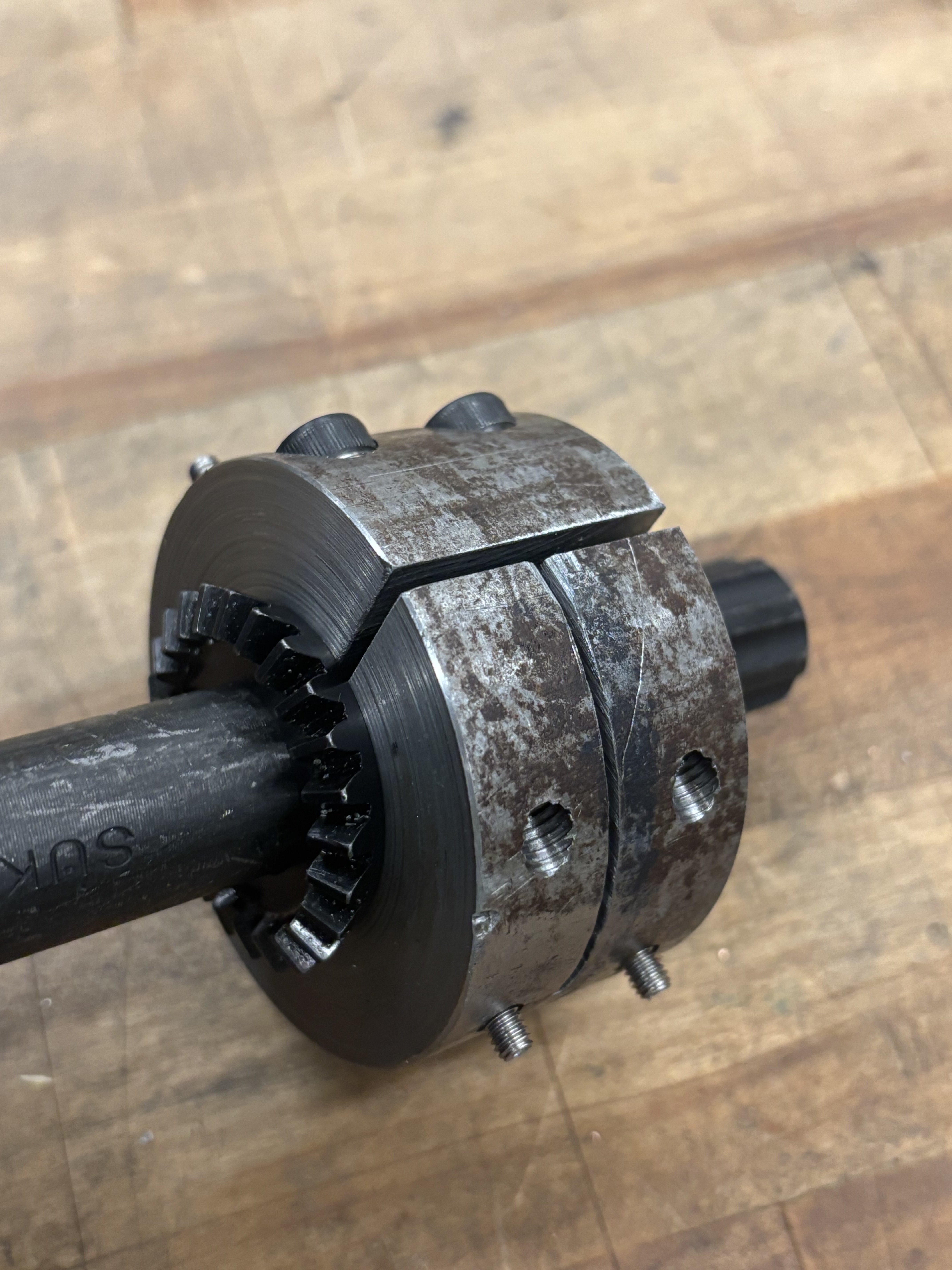
The machined step-down collar

Part 5: manufacturing & results

5. Cutting it and proving it

  • Worked directly with a machinist to CNC the components, then test-fitted and validated the assembly on the bench before integration.
  • 50% reduction in gearbox weight versus the previous design.
  • Gear slippage eliminated — no measurable loss under full pilot load.
  • Parts came off the CNC to spec and assembled without rework.

The biggest lesson wasn't the analysis — it was how much manufacturing constrains design. Talking to the machinist early changed my geometry more than any simulation did, because a part you can't fixture is a part you can't make.

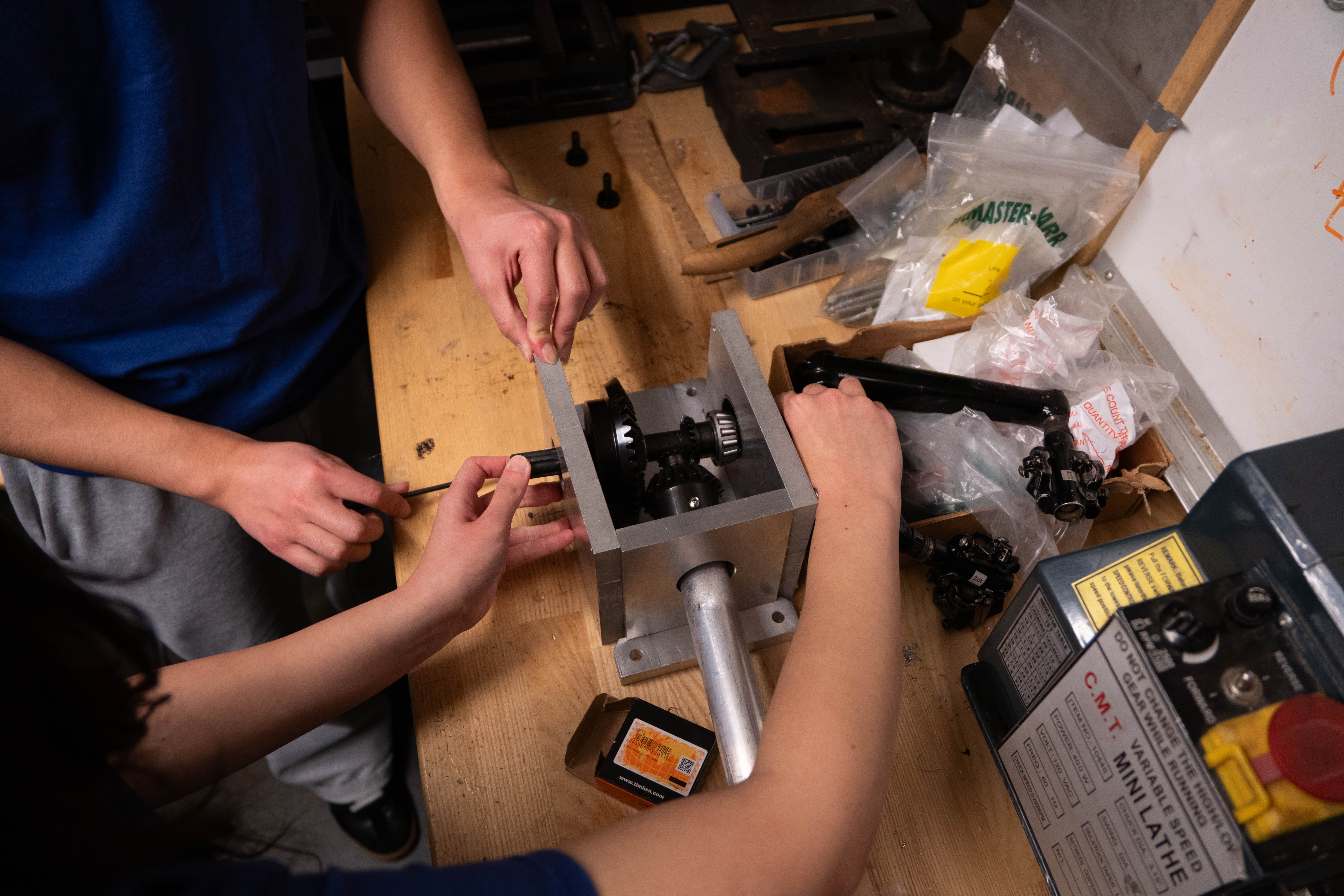
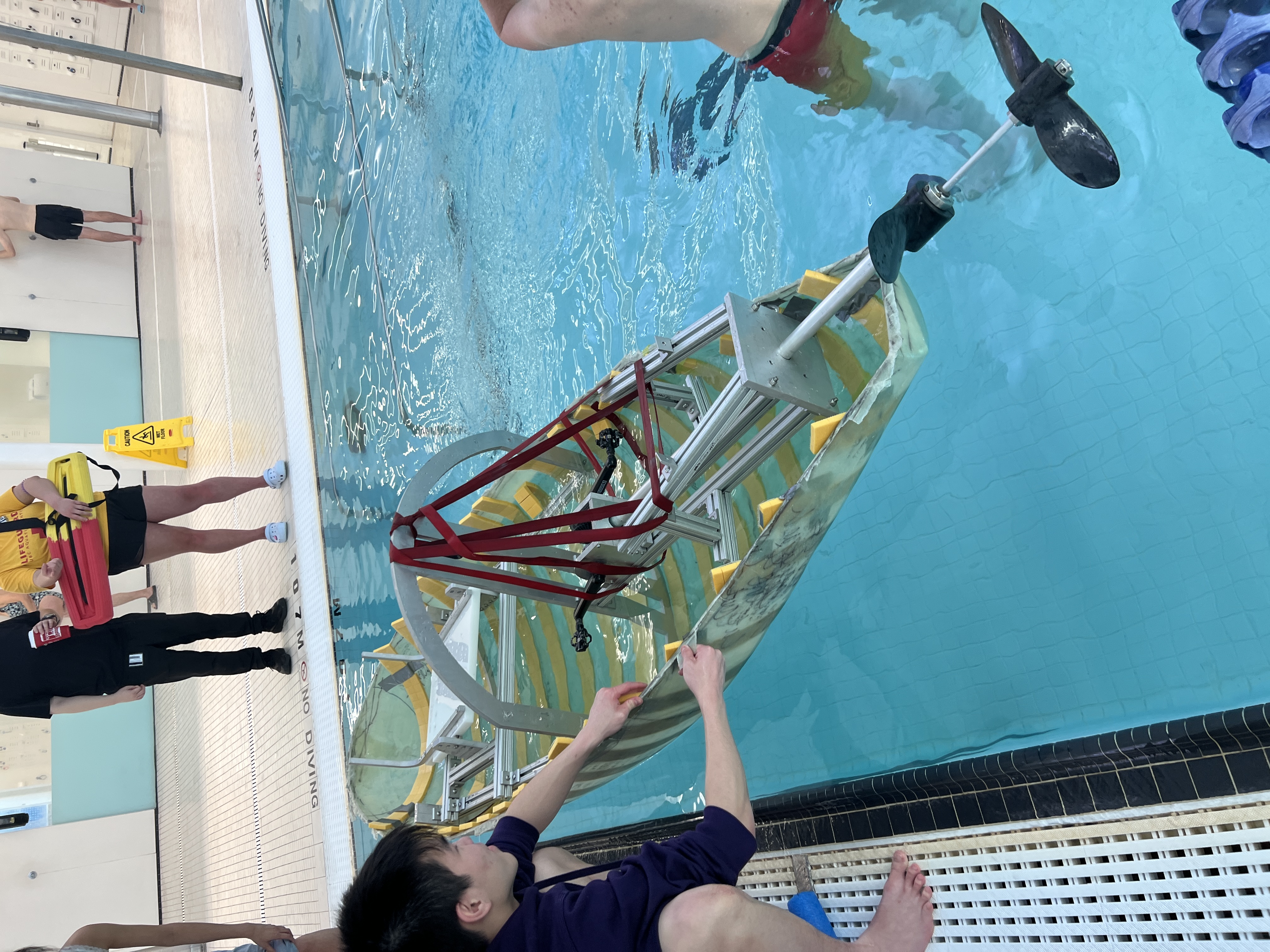
The finished machined components