LS Laird Scabar
All projects Project 01 · HVAC & industrial

Make-Up Air Unit Relocation

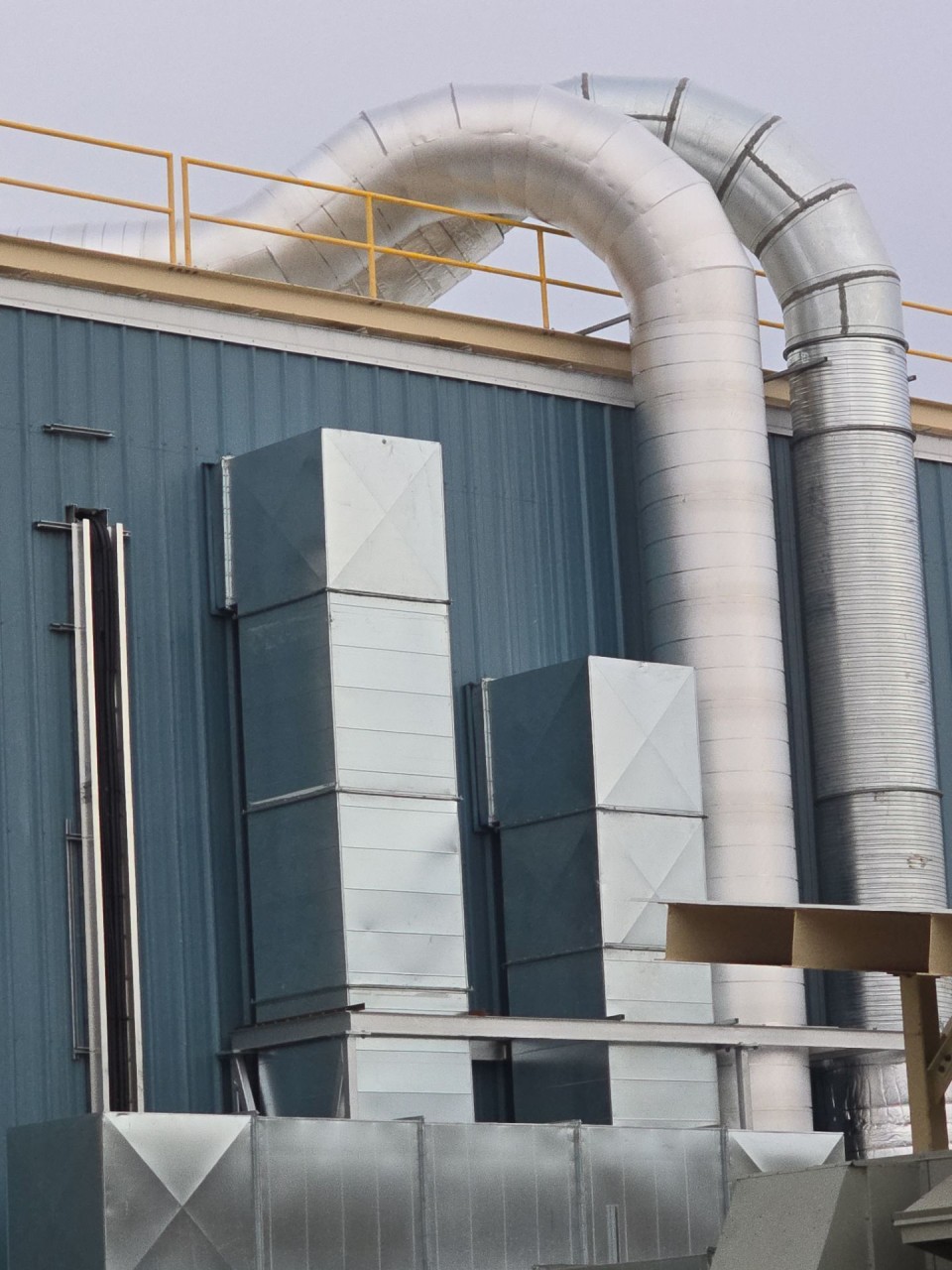
Four make-up air units, two per building, had to come off the roof because condensation was leaking into the electrical rooms underneath them. I designed the duct rerouting that reconnected them, and the steel that holds it up.

Where
VETS Group internship
Units relocated
4 (2 per building)
Codes
SMACNA · ASHRAE
My role
Design through shop handoff
Longer, in-depth explanation Flip the switch for the full engineering breakdown

Quick explanation

What it is

  • Four make-up air units, two on each of two buildings, sat on the roof above the electrical rooms below, and condensation from them was leaking into those rooms. Moving the units was the fix.
  • That meant rerouting both the supply and the return air for all four units and tying everything back into the existing duct systems.
  • I designed the new routing to SMACNA and ASHRAE, working off the existing drawings and a point cloud scan of the site.
  • I specced the duct gauge and the minimum supports along every run, and designed three 15 ft duct support towers rated for 1.5 tons each, plus the smaller supports at grade and on the roof.
  • I ran it from design through drawings and the model, then handed it to the shop, who fabricated and installed it.
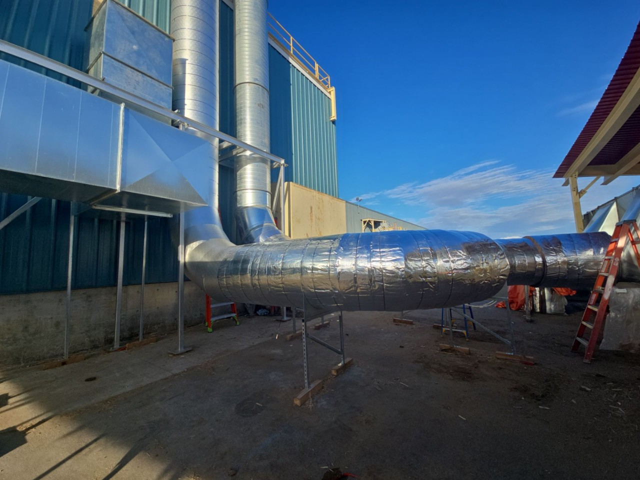
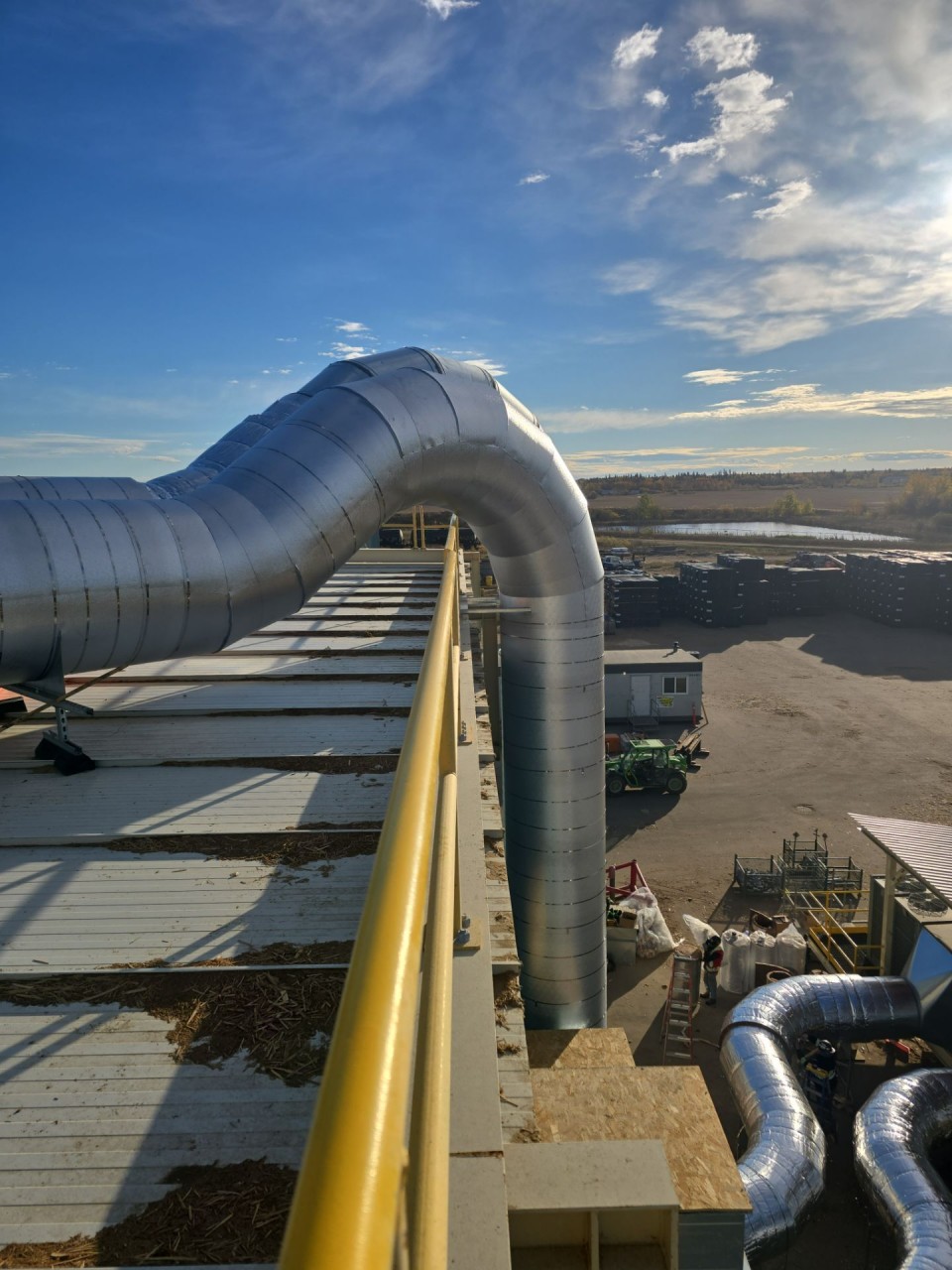
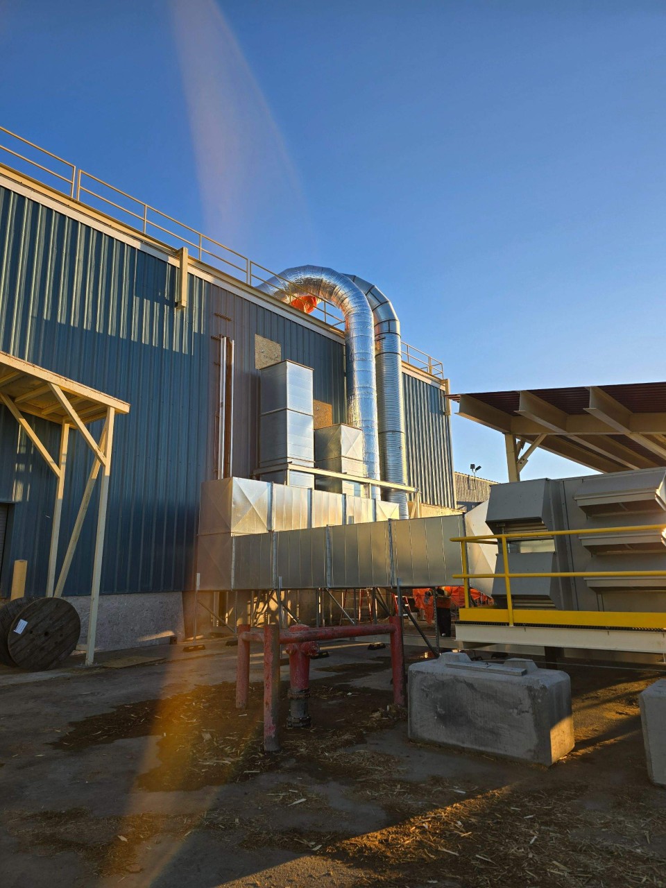
The finished insulated duct run on its supports

Deep dive

How the reroute came together

Part 1: the problem

1. Water where the electrical gear lives

  • Four make-up air units were mounted on the roof, two on each of two buildings, sitting above the electrical rooms below.
  • Condensation off the units was leaking down into those rooms, which is about the worst place in a plant for water to end up.
  • The fix was to get the units off the roof entirely, which turned a water problem into a ducting problem.
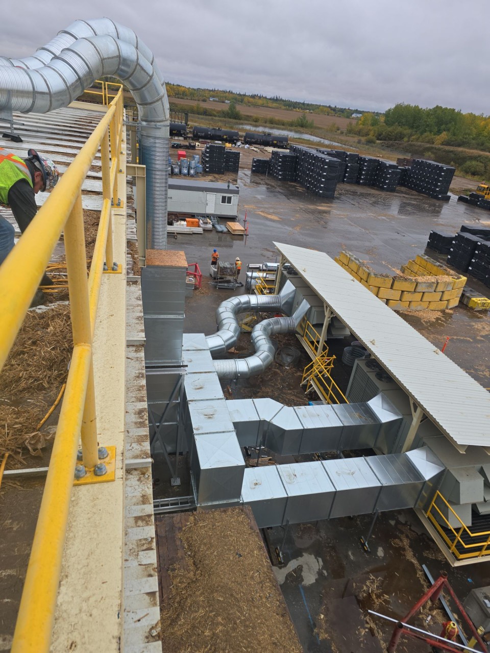
  • Each unit moves supply and return air, so every path had to be rerouted and reconnected into duct systems already in place, eight connections across the two buildings.

Part 2: designing into what already exists

2. Existing drawings and a point cloud

  • There was no blank sheet here. The routing had to fit the building as it actually stands, so I worked from the existing drawings plus a point cloud scan of the site.
  • The scan is what catches the things drawings miss: structure, equipment and services sitting exactly where you wanted to run duct.
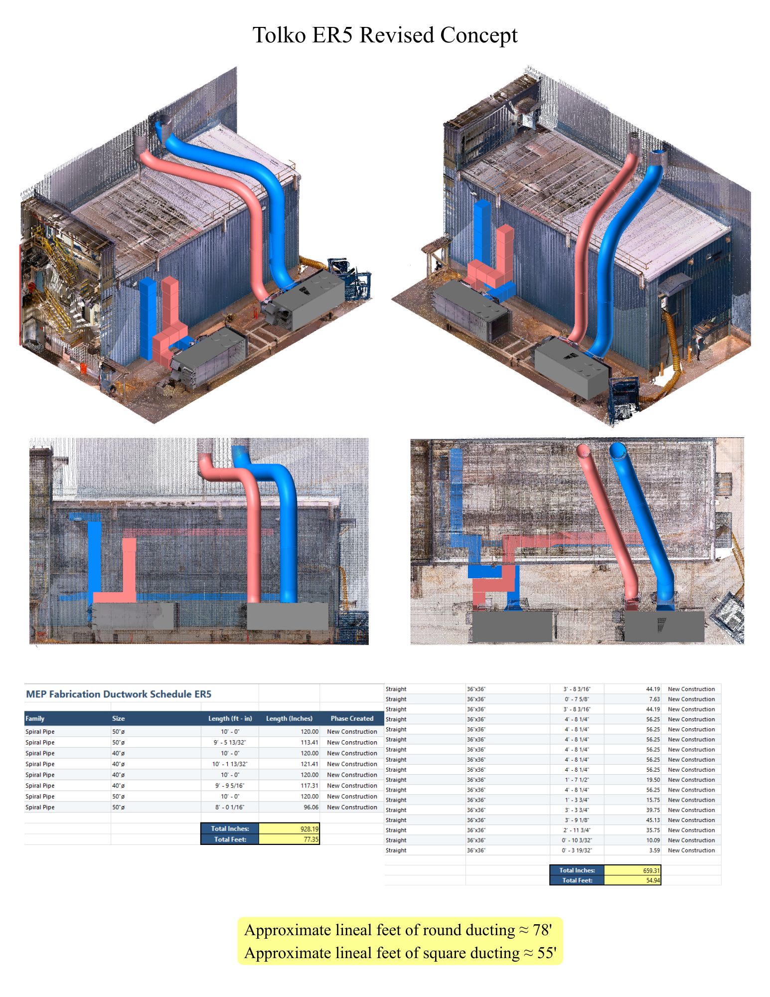
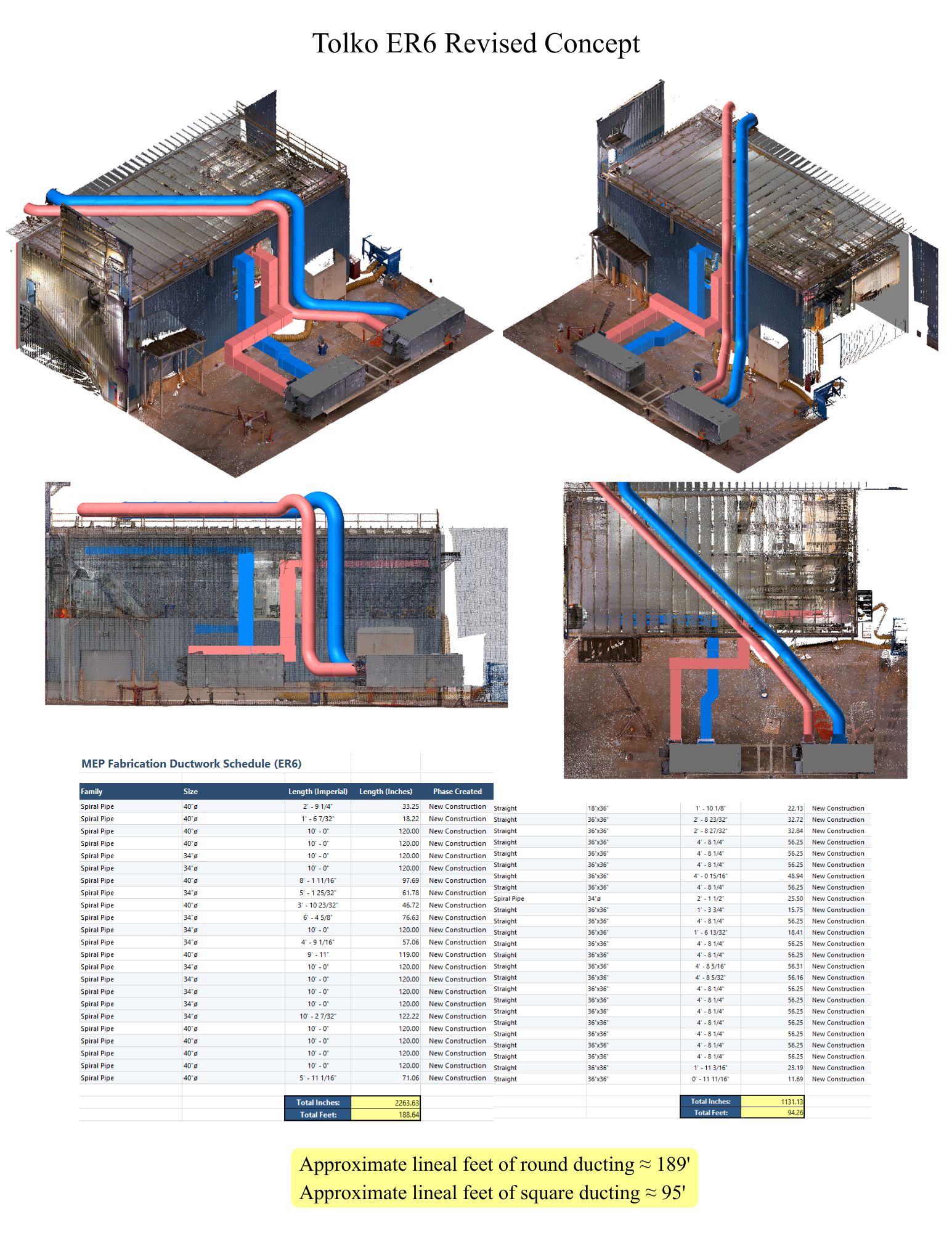
  • I modelled the new runs against that, then picked the fittings and transitions needed to land cleanly on the existing connection points.
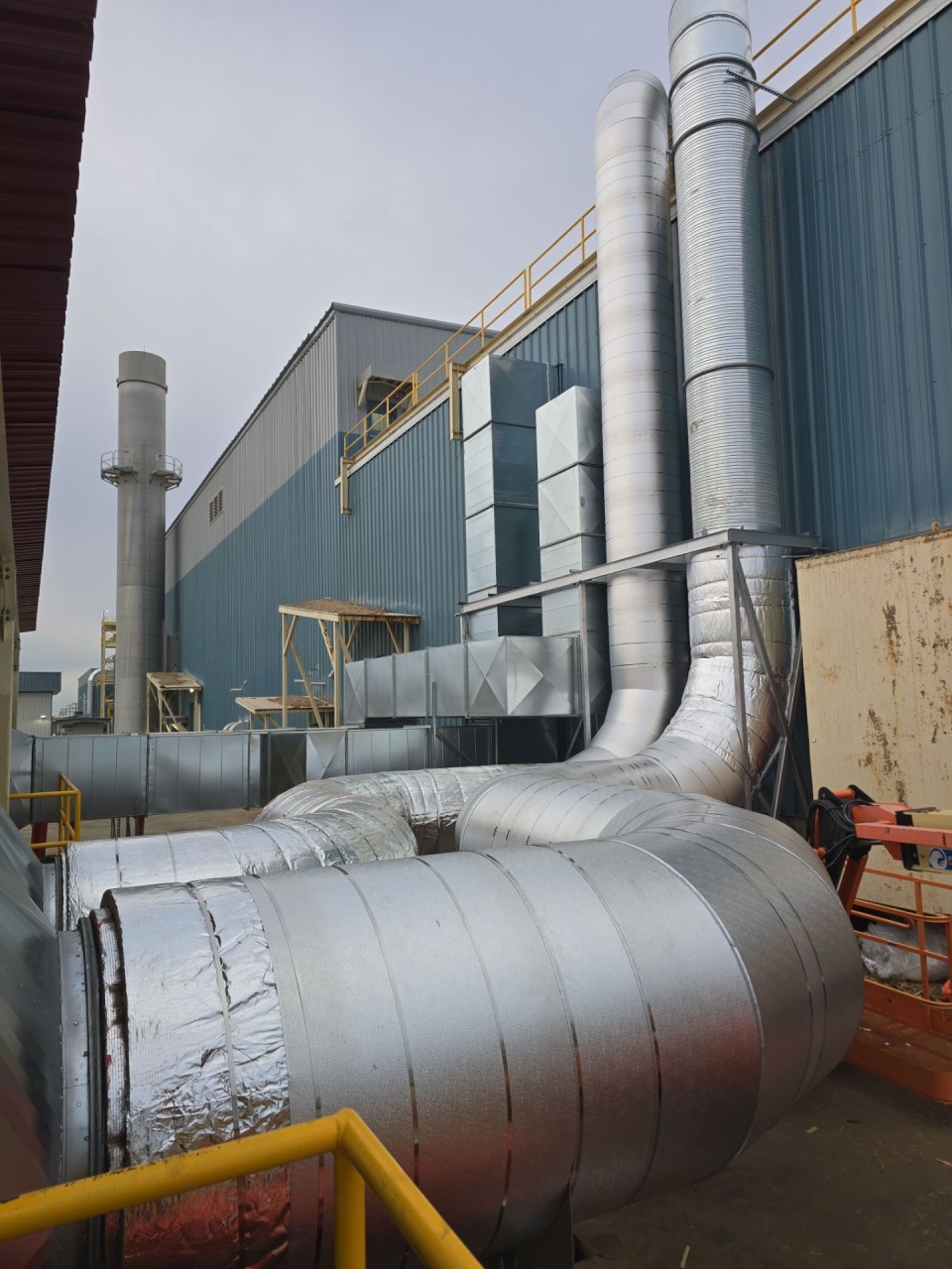
  • The duct is multi-size double-wall, so every transition had to account for the insulation thickness as well as the airway size.
  • I took the quantities off the model as a ductwork schedule for each building: roughly 78 ft of round and 55 ft of square duct at ER5, and 189 ft of round and 95 ft of square at ER6, in sizes from 34" to 50" spiral and 36"x36" rectangular.
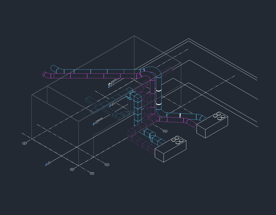
AutoCAD isometric of the rerouted duct

Part 3: sizing the duct itself

3. Gauge and supports to SMACNA and ASHRAE

  • The whole system was designed against SMACNA and ASHRAE, which is what sets the gauge, reinforcement and support rules for duct this size.
  • I specced the duct gauge run by run, since the sizes change along the route and the requirement changes with them.
  • I worked out the minimum supports needed at every point along the system rather than just at the obvious spans.
  • Double-wall duct is heavy. The insulation and inner liner are what drive both the gauge call and the support spacing.
Insulated duct mains between the buildings

Part 4: holding it all up

4. Three towers and everything underneath

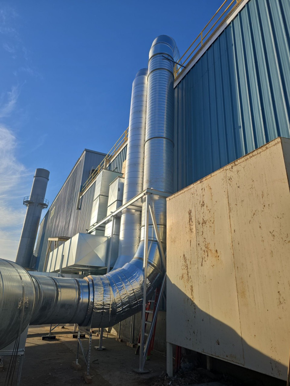
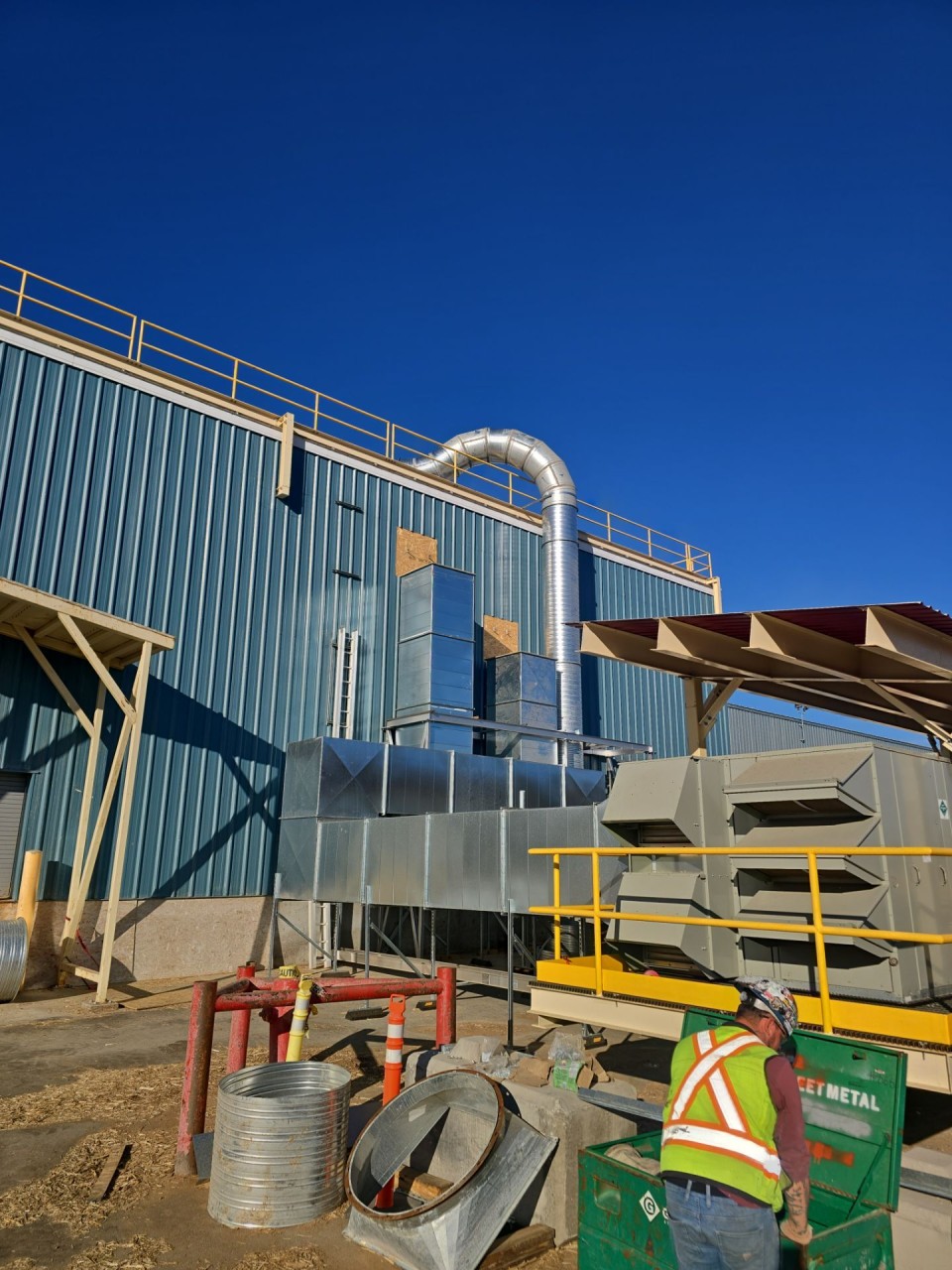
  • I designed three structural duct support towers, each 15 ft tall and rated for 1.5 tons. They're the steel standing against the building wall in the photos.
  • I also designed the smaller supports at grade and on the roof, all sized from the system weight they carry.
  • Sizing comes from the duct itself: the sheet metal, the insulation, and what the span between supports does to the load on each one.
  • Getting this wrong doesn't show up on paper, it shows up as a sagging main a year later, so the support design mattered as much as the routing.
Duct support towers against the building wall

Part 5: the tight bit

5. Ten feet of double-wall duct, indoors

  • The system penetrates the building and runs about 10 ft internally before it ties in.
  • That space is tight, and thick double-wall duct doesn't bend around problems. The outside dimension is what it is.
  • Packing that run in, with the fittings it needed and clearance to actually install it, was the fiddliest part of the design.
Duct penetrating the building wall

Part 6: revisions and handoff

6. Four rounds, then over to the shop

  • The system went through roughly four revisions: client comments, feedback from the team, and obstructions nobody knew about until someone looked.
  • I handled it from design to drawings to the model, then passed the package to the shop.
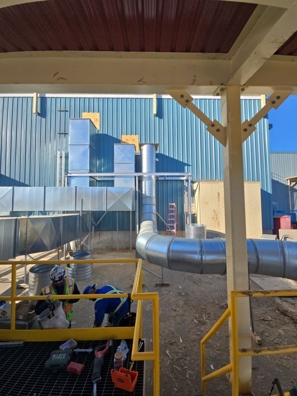
  • The shop fabricated and installed it. The site photos here are their work built off my drawings.
  • Working to a package someone else has to build from is a different discipline than designing for yourself. If it isn't clear, it comes back as a question, or worse, as a part that doesn't fit.
Sheet metal crew on site during installation